Announcements
You are advised to check this section regularly.
EST Answer Sheets
May 23, 2018
After MST Quiz
May 2, 2018
Lab Manuals
May 2, 2018
Tutorial Solutions
May 1, 2018
MST Answer Scripts
April 3, 2018
Quiz Marks
Students are advised to view marks according to their groups.
Course handout
This covers the complete syllabus of UEC301 course.
Course objective:
- The aim of this course is to familiarize the student with the analysis and design of basic transistor amplifier circuits, oscillators and wave shaping circuits.
Course learning outcome (CLO): The student will be able to:
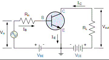
- Analyze different biasing circuits and low frequency response of an amplifier using h parameters.
- Develop an ability to analyse high frequency transistor model.
- Explain various multistage and power amplifier configurations.
- Explain the concept of feedback and its characteristics.
- Explain the principles of oscillation and design various oscillator circuits.
- Analyse various filters and multi-vibrators circuits.
Detailed Syllabus:
- Transistor Biasing: The Operating Point, Biasing Stability, Self-Biasing or Emitter Bias, Stabilization against Variations in ICO, VBE, and β, Bias Compensation, Transistor at Low Frequencies: h parameter, simplified CE hybrid model, analysis of a transistor amplifier circuit using h parameter.
- Transistor at High Frequencies: The Hybrid-pi (II) Common-emitter Transistor Model, Hybrid-II conductances, The Hybrid-II Capacitances, analysis of a transistor amplifier circuit at high frequencies.
- Multistage Amplifiers: Classification of amplifiers, Distortion in amplifiers, Frequency response of an amplifier. The RC-coupled amplifier, Low-frequency response of an RC-coupled stage, Effect of an emitter Bypass capacitor on low-frequency response.Class A, B, AB, Push pull & Class C amplifiers, Comparison of their Efficiencies, Types of distortion.
- Feedback Amplifiers: Classification of Amplifiers, The feedback concept, The transfer gain with feedback, General characteristics of negative-feedback amplifiers, Input resistance, Output resistance, Block diagrams of Voltage-series feedback, Current-series feedback, Current-shunt feedback, Voltage-shunt feedback.
- Stability and Oscillators: Sinusoidal Oscillator, The phase-shift oscillator, Resonant-circuit oscillators, A General form of oscillator circuit, The Wien Bridge oscillator, Crystal oscillator, Frequency Stability.
- Wave shaping circuits: Multi-vibrators (Astable, Mono-stable, Bi-Stable), High pass and low pass filters using R-C Circuits and R-L, R-L-C Circuits & their response to step input, Pulse input, Square input and Ramp Input, Attenuators.
Laboratory: Frequency response analysis of RC coupled amplifier, Tuned amplifiers, Push-pull amplifier, Feedback amplifier.Hartley and Colpitts Oscillator. RC Phase shift oscillator. Study of Multi-vibrators (Astable, Mono-stable, Bi-stable Multi-vibrator). Clipper and Clamper circuit, Schmitt Trigger.
Text Books:
- Milliman, J. and Halkias, C.C., Intergrated Electronics, Tata McGraw Hill (2007).
- Milliman, J. &Taub, H., Pulse, Digital and switching waveforms, Tata McGraw Hill (2007).
Reference Books:
- Malvino, L., Electronic principles, Tata McGraw Hill (1998).
- Cathey, J. J., 2000 Solved Examples in Electronics, McGraw Hill (1991).
Marks Distribution
| # | Examination | Marks |
|---|---|---|
| 1 | LAB | 15 |
| 2 | QUIZ | 20 |
| 3 | TUT | 05 |
| 4 | MST | 24 |
| 5 | EST | 36 |
| T O T A L : | 1 0 0 |
Tutorial Sheets
Course tutorial sheets with solution.
Power circuits: Systems
Tutorial Sheet 8
Oscillators-1
Tutorial Sheet 9
Lab Experiments
Lab Manuals for all the experiments of this course.
Experiment 1
Use of Astable Multivibrator and Calculate the frequency by changing the base resistance/capacitance.
DownloadExperiment 2
Use of Monostable Multivibrator and find the pulse width by varying the value of base resistance Q2.
DownloadExperiment 3
Plot timing diagram of Bistable Multivibrator and use it as divided by two unit.
DownloadExperiment 4
Operation of Hartley and Colpitts Oscillatorand the effect of variation in amplitude and frequency with C.
DownloadExperiment 7
Draw Push-Pull Amplifier circuit. Measure the output impedance and also find the Bandwidth of a Push-Pull amplifier.
DownloadExperiment 8
Design and study RC phase shift oscillator. Find the Frequency and compare with calculated frequency.
DownloadExperiment 9
Top plot the frequency response curve of a tuned amplifier and determine its bandwidth.
DownloadExperiment 10
To observe the property of current series feedback amp using CE transistor amp with an unbypassed emitter resistor.
DownloadExperiment 11
To study the two stage R.C. coupled amplifier and 1)Find its bandwidth 2)Find i/p and o/p impedance
DownloadLearning Resources
Explore the below course reference material.

Multivibrators
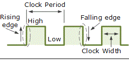
These are sequential logic circuits that operate continuously between two distinct states of HIGH and LOW.
Learn more
Course Instructors
UEC301 Analog Electronics Faculty


